Votesen VLS722 ULM device Understanding and Protocol debugged.docx

Votesen VLS722 ULM device Understanding and Protocol debugged.docx

Administrator
|
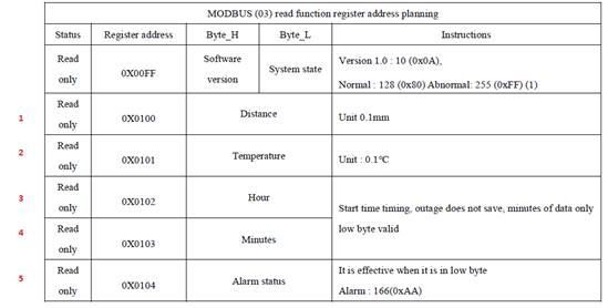
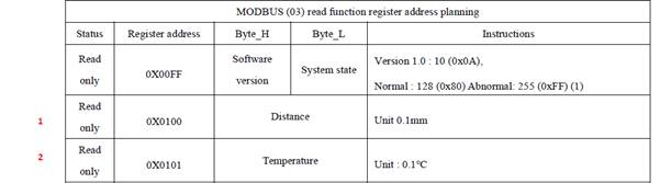
Votesen VLS722 ULM device Here is the key data to interface to the device The Signal Strength and the Level and Temp are in two commands; Get Signal Strength Command First byte: Device ID Second Byte: Command Third & 4th Byte: Register 5th & 6th Byte: Number of registers read. 7th & 8th: CRC (W HEX) [8] 01 03 01 0D 00 01 14 35 Response First byte: Device ID Second Byte: Command Third Byte: Payload Length Fourth & 5th Byte: Data (001E) Sixth and 7th: CRC (R HEX) [7] 01 03 02 00 1E 38 4C =================================================================================== Get Level &Temp Command (5 registers) (W HEX) [8] 01 03 00 FF 00 05 B5 F9 First byte: Device ID Second Byte: Command Third & 4th Byte: Register 5th & 6th Byte: Number of registers read. 7th & 8th: CRC (R HEX) [15] 01 03 0A 0D 80 FF FF 01 24 00 03 00 24 15 4C
Get Level &Temp Command (2 registers) This is a better commands we don’t need the other data, just Level and Temp (W HEX) [8] 01 03 00 FF 00 02 F4 3B First byte: Device ID Second Byte: Command Third & 4th Byte: Register 5th & 6th Byte: Number of registers read. 7th & 8th: CRC Response (R HEX) [9] 01 03 04 0D 80 FF FF F8 C7
�Black core wire, sensor supply wires, connecting power supply negative pole �Green core wire, sensor signal wires, the signal wire is marked as RX/A and connecting to the TX/A end of the user device �Yellow core wire, sensor signal wires, the signal wire is marked as TX/B and connecting to the RX/B end of the user device
How to change the address of the Probe The address change instruction is: 00 06 01 07 (**) (checksum) “00060107B6B8” 1. (**) Please enter the address you want to change 2. (Checksum) Please replace MODBUS checksum Alternately if you don’t know the Address, you can use a broadcast mode (1 device connected) to change the Address (W HEX) [8] FF 06 01 07 00 01 ED E9 (R HEX) [8] FF 06 01 07 00 01 ED E9 Understanding the protocols It is always important to know the default address of the ATG supplier. In this case it was suppose to be 01 but it turned out to be 00 – the reset of the explanation will be done with this address. Broadcast Command to determine Address of a device (W HEX) [8] FF 03 00 FF 00 05 A0 27 (R HEX) [15] FF 03 0A 0D 80 FF FF 01 20 00 02 00 0C E3 2D This did two things;
This is the command to specifically get the address; (W HEX) [8] FF 03 01 07 00 01 21 E9 (R HEX) [7] FF 03 02 00 01 50 50 Command to determine the Level only for address 00 00 03 01 00 00 01 84 27 - This is the read distance value to read the liquid level height. (W HEX) [8] 00 03 01 00 00 01 84 27 (R HEX) [7] 00 03 02 FF FF 84 34 The height is given by “FF FF” Command to determine all relevant data 01 03 00 FF 00 05 B5 F9 - continue read 5 register address instructions. This is to read the sensor working time, temperature, liquid level height, version (W HEX) [8] 01 03 00 FF 00 05 B5 F9 (R HEX) [15] 01 03 0A 0D 80 FF FF 01 20 00 02 00 0D 74 92 01 Address 03 Read function code 0A Version 0D 80 Software version FF FF Distance- 01 20 Temperature 00 02 hours 00 02 minutes 74 92 checksum |

| Free forum by Nabble | Edit this page |